Reinforcement Learning Agent
This project was about testing different reinforcement-learning algorithms. After going through the lecture notes of David Silver’s (DeepMind) UCL course on reinforcement learning, I wanted to apply the methods to a game that was i) simple enough to train on my single GPU and ii) fun and a bit out of the ordinary.
I picked the Royal Game of Ur because it’s a game that had been played for literally thousands of years but hardly anybody plays it or even knows about it today. So any strategies that might have been common ~3000 years ago have probably been forgotten – which made this game an interesting choice.
I implemented and tested pretty much all methods covered in David Silva’s lecture. Specifically, I implemented
- Q-Learning with Monte Carlo, Temporal Difference (td0 and tdn) and TD-Lambda, both on- and off-policy,
- Policy-Gradient with Monte Carlo, and
- Actor-Critic with Monte Carlo, Temporal Differences (td0 and tdn) and TD-Lambda. The Monte Carlo method was implemented on- and off-policy.
Of these methods on-policy Q-Learning with Monte Carlo (q_mc) resulted in the strongest player. You can find the code and weights to play against my best model here.
The game involves a lot of luck so a good strategy can only do so much. But when I first played against the q_mc agent I ended up losing most games. Once I got into the game I started winning about 50% of the games (or maybe a bit more often).
I also used the code to create an agent for a common version of the game Mancala. It’s available in the same repository but it doesn’t include a GUI or any weights.
Tech: JAX, Haiku (training), Python (sample creation)
Paper: Variable-Input Deep Operator Networks
This is a paper that resulted from my time as a Research Assistant at Prof. Dr. Mishra‘s group at the ETH. Our objective was to create a machine learning model that can learn the solutions to partial differential equations (PDEs) whose observations are given on an irregular grid. My main responsibility was the model structure and implementation. You can find the code on github.
Tech: PyTorch (training), TensorBoard (visualization), C++ / Python (training data creation)
Creation of a Video Streaming Site

In this project I created a highly optimized video streaming website that contains some of my YouTube videos and other content. The website is available in multiple languages and it features a secure login section for watching premium content (currently populated with placeholder data).
The back end is written with flask, the front end with HTML, CSS and JavaScript. The layout of the video page is created with flexbox. The backend is deployed on AWS’s Elastic Beanstalk. The front end, videos and other data is saved in S3 buckets. I also use ElastiCache for server-side caching of often-used assets and a PostgreSQL database for persistent storage. The entire website sits behind the CloudFront CDN which results in fast loading. The entire stack is defined using AWS’ Cloud Development Kit so it can easily be adjusted or recreated if required.
I wrote this page and set it up AWS in about 10 days with help of an LLM. The LLM made the coding process a lot faster but it really struggled once the code base became a bit larger. At times it also suggested wrong or inefficient code so my own code-understanding and practice with debugging was very important to get this up and running quickly.
Tech: Flask / Python (backend), HTML, JavaScript, CSS (frontend), AWS (infrastructure)
3D-Reconstructions
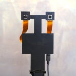
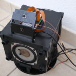
This is a large, ongoing project where I’m developing a machine to automate 3d-reconstructions of small objects. A short video about the first prototype, which uses photogrammetry, is shown on the right.
The first prototype uses mostly components that I already had at home: a camera intended for photography (Fuij X-T2), stepper motors, timing belts, 3d-printed parts to connect everything, and an Arduino and a Raspberry Pi to control everything.
This first prototype uses photogrammetry so it works well for objects whose surfaces have lots of features. Homogeneous or highly reflective surfaces are not reconstructed well due to a lack of features.
The actual reconstructions use a mix of code that’s already implemented in the open-source program Meshroom and of code that I wrote to extend Meshroom. While I’ve read most papers that describe the methods used in Meshroom (e.g. SfM and MVS), I didn’t implement those myself. My extensions focused mostly on using the known camera position from my machine and on aligning multiple scans from different sides.
For the second prototype I’m planning to use an industrial machine vision camera, a liquid lens for fast focusing, and a combination of different methods, such as Photometric Stereo, to ensure reliable reconstructions for homogeneous or reflective surfaces. The plan is to implement them in a high-performance C++ code (not using Meshroom).
Tech: Docker / CMake (compilation), C++ / Python (code adjustments and extensions), Arduino Language (controlling hardware), Python (coordinating camera and hardware)
Computer Vision Theory
As I’ve been developing the machine to automate 3d-reconstructions, I’ve delved deeply into some theory related to computer vision. For example, getting an accurate reconstruction requires an accurate calibration of our camera. So we want to find the focal length, principal points, distortion coefficients, etc. Choosing an appropriate camera and lens (for the second prototype) requires an understanding of image resolution (the system’s ability to resolve details) and the factors that affect it.
When I dig into theory I usually write summaries to explain the topic in detail. Writing summaries helps me memorize concepts and it exposes holes in my reasoning.
I’ve turned some of my summaries into videos that try to explain ideas without going too much into mathematical details. On the left there’s a video where I derive the camera matrix from the pinhole model. Here you can find a video about image resolution and contrast, and about how diffraction, lens aberrations and our sensor affect it.
Tech: Blender (Visualization), OpenCV (Image Processing)
Smaller Computer Vision Projects
Below are two smaller projects that didn’t require as much time as the other projects on this page.
Stereo Vision and Semi-Global Matching
Semi-Global Matching is a common algorithm used in 3d-Reconstructions and in Stereo Vision. I wanted to learn more about it and to get some hands-on experience with it. So after reading Mr Hirschmüller’s paper I built a simple stereo setup, using two Raspberry Pi Camera Modules v3 and a Raspberry Pi 5. Then I calibrated them and I used OpenCV to implement the computation of disparity maps and point clouds. Since the quality of the output depends heavily on the values of the parameters used in SGM I built a GUI to tune them. Visualization of the point cloud is done with Open3D. See this blog post for more details.
Tech: Python (general and camera control), OpenCV (Image Processing), Matplotlib / Open3D (visualization)
YOLO against Pigeons
This is a small project where I use YOLO to keep pigeons away from my balcony. Apparently pigeons can hear much lower sound frequencies than humans. While most humans can hear down to about 20Hz, pigeons can hear much lower frequencies. So I set up a Raspberry Pi with two cameras and I periodically (every 10 seconds) capture the balcony. The images from the two cameras are fed into the pre-trained YOLO v5 model from Ultralytics. If any pigeons are detected then the RPi plays a random low-frequency wave in the range of 7Hz to 15Hz at maximum amplitude. The sound wave is inaudible to (most) humans but the pigeons take flight immediately. After 5 seconds my cameras take another set of pictures and if no pigeons are detected then the sound stops playing. Since the two cameras can’t capture the entire balcony at once I’ve put the entire device on a turntable with a servo motor underneath it. The search for pigeons is repeated at a set of different rotation angles such that the entire balcony is covered. The pre-trained model can’t detect pigeons specifically, it only has a category birds. That’s ok in my case because pigeons are the only birds that visit my balcony.
Tech: Python (servo and general control), PyTorch / YOLO (object detection)
DIY Digital Spectroscope
In this project I combined an analogue pocket spectroscope and a digital camera to get a DIY digital spectroscope. This was a challenging project because I didn’t know how exactly the analog pocket spectroscope worked on the inside. So to get reliable results I had to do lots of tests so I could infer how the analog spectroscope works.
Since I was using a camera intended for photography (not a mono camera), there was a color filter array on top of the sensor. So each pixel is only sensitive to a subset of all the light that reaches the sensor (+ there’s an IR cutoff filter). To be able to measure the entire visible spectrum I had to combine the signals from the three RGB measurements, which required a lot calibration.
Calibrating the digital spectroscope was another big challenge. While the calibration of wavelengths (i.e. the horizontal axis on a chart showing the measured spectrum) can be done relatively easily by using the known spectral lines of the sun, their relative intensity is not as obvious because it requires a light source with a known, relatively flat, spectrum. If you’re interested in the details then please check out the video, it contains lot’s of information about the calibration process.
The code that generates the digital spectrum from an image taken by the camera can be found here.
Tech: Python / OpenCV (image processing), tkinter (visualization)
Simulation of a CNC-Machine
In this project I wrote a simulation of a CNC-Machine. The input to the program is
- a file containing the G-Code that you want to run,
- the drill-bit that you want to use and
- a 3d model of the workpiece that you’ll cut into.
The simulator then runs the code and outputs a 3d model of the finished workpiece. The exact shape of the workpiece depends on the drill bit that you’ve chosen, just like on a real CNC-Machine.
The simulator also simulates the movement of the parts of a simplified CNC-Machine. During the simulation it checks if there are any collisions between (non-cutting) parts of the machine and the workpiece and it prints a warning if that’s the case. To find the correct cuts I use a sweeping algorithm. So I use the drill profile at the beginning and at the end of a movement and connect them appropriately to get a mesh of the whole cut. This mesh is then subtracted from the workpiece. This boolean operation becomes expensive for complex geometries. So I’ve split the workpiece into smaller segments and I compute the boolean on each segment that overlaps with a machine part (in parallel). The simulation works in full 3d space with arbitrary drill bit geometries.
There are a lot more efficient algorithms for simple 3-axes machines like the one I’ve implemented here. This simulator is not intended to replace them. Rather, I created it as a proof-of-concept for more complicated machines (e.g. robot arms with many axes). Since its core functionality works in full 3d space it could readily be extended to cover machines with arbitrary moving parts.
The code uses the C++ library manifold for fast boolean operations with guaranteed manifold output. I’ve written the core of the program in C++, parallelization uses OpenMP. The command line version of the simulator runs the C++ code directly. The GUI version is written in Python with VTK/Qt6 and it accesses the C++ code via Python bindings.
Tech: C++ (computation), OpenMP (parallelization), Python / VTK / Qt6 (visualization)